-
In this section, the application of advanced design techniques and of optimization are considered. Aggressive design of turbomachinery components is concerned. The optimization strategy is based on the coupling of non-traditional design techniques as inverse methods and adjoint optimization.
The adjoint solver drives the inverse design procedure to optimal configurations, while it avoids the well-posedness issues. In fact, the inverse solver and the optimizer are based on the flow governing equation and on its adjoint. -
Design of Optimal Diffusers.
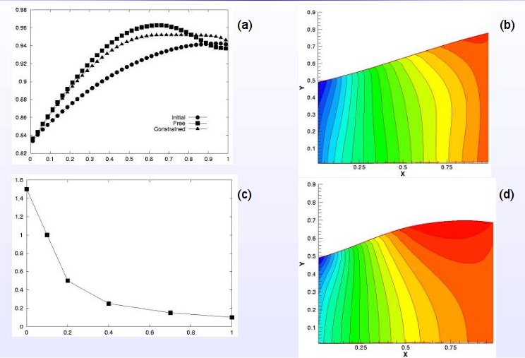
Design of a flow separation resistant diffuser with minimum deviation at the outlet. The shape of the diffuser with uniform outflow direction is sought. To avoid flow separation in the full range of working conditions, the pressure gradient at wall is constrained according to a separation criterion. The computational approach is based on a continuous adjoint optimization that drives the sequence of inverse problems. In Figure 1(a) the pressure distribution of the diffuser wall is displayed. The initial pressure distribution corresponds to the diffuser geometry of Figure 1(b), obtained by solving an inverse problem. The optimal pressure distribution corresponds to the solution of Figure 1(d).
-
-
FIGURE 1: Diffuser with minimum outlet deviation. (a) Pressure distribution at wall during the optimization process. (b) Initial diffuser geometry, (c) constraint on the maximum pressure gradient along the diffuser wall, (d) optimal diffuser.
-
Simultaneous Design of Multistage Axial Compressors or Turbines
-
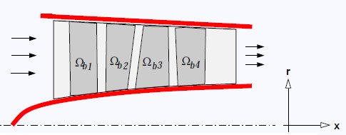
A modelling approach for deriving the flow inside a multistage axial gasengine is presented in this section.
By introducing the axis-symmetry hypothesis, the Euler equations are reduced to a quasi-2D formulation. Therefore, the flow inside an axial turbomachine can be represented into the meridional plane. In present model, the action of stator and rotor blades are replace by volume forces. If an analysis problem is concerned, given the blade geometry the blade forces are found. In the design problem instead, we prescribe these forces nd the blade shape is found by solving an Inverse Problem. Since the geometry of all the blades,i.e. rotors and stators, are found simultaneously, the flowfields generated by the blades are automatically in accord each other. The numerical approach follows the footsteps of the previous case. A numerical solution of the continuous adjoint of this flow problem has been derived. The adjoint solver is used for finding optimal blade force distributions. The shape of the blade camber surfaces are then obtained simultaneously, by solving the inverse problem. Viscous effects, blade blockage and losses are taken into account by distribute loss models. -
-
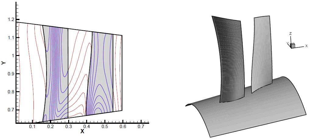
FIGURE 2: Aft-swept fan rotor. Pressure field (a) and blade geometry (b). The gray regions represent the blade projection onto the meridional plane, i.e. the blade planform.
-
-
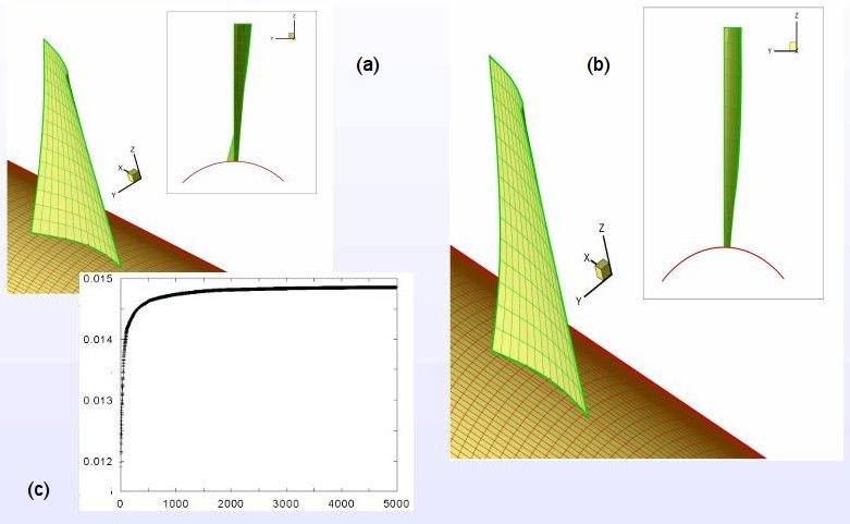
FIGURE 3: The optimization of an unducted propfan at flight Mach number M=0.6 . (a) Initial guess, (b) optimal geometry, (c) thrust versus optimization steps.
-
-
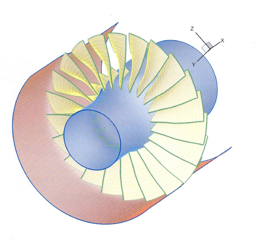
FIGURE 4: Optimization of transonic fan for lowering the noise. Starting point was the NASA rotor 37.
-
Inverse Problems in Fluid Dynamics
read MORE » -
Thermal Design of Cooled Turbine Blades
read MORE »
back to RESEARCH »
TURBOMACHINERY DESIGN & OPTIMIZATION
