-
5th Standard Aeroelastic Configuration.
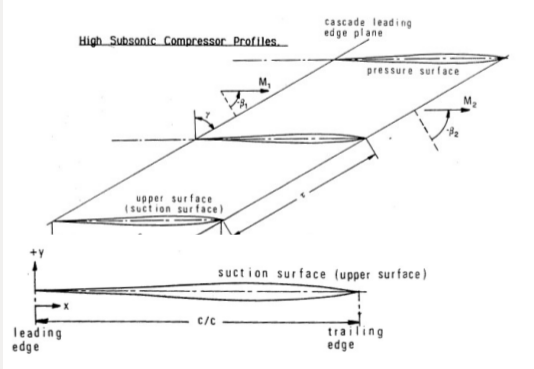
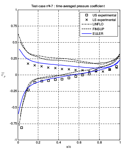
The aeroelastic analysis is based on the simulation of the blade row dynamics by using the unsteady Euler/Navier Stokes equations in time-varying domains. As an example we propose here the inviscid computation of the 5th Standard Aeroelastic Configuration, a good test-case for comparing a numerical tool against theoretical and experimental data. The test-case focus on a compressor cascade with symmetric blade profile at high subsonic Mach numbers. Various subcases are treated,with different working conditions but the same geometry.
FIGURE 1:
Mean pressure coefficient along the blade (Test-case n. 4-7) -
Fluid-Structure Interaction: a 2-D Approach for Blade Cascades.
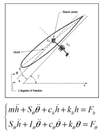
In this case the unsteady aerodynamic forces and the blade motions must be computed at once. To the fully unsteady aerodynamic solver is therefore coupled either a structural solver, or a dynamic model for the blade motions. For the 2-D case, the "Typical Section" approach is adopted.
FIGURE 2:
Dynamic model for the blade with two-degrees of freedom. -
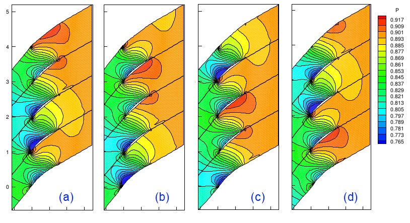
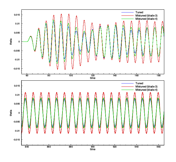
In this section the results of the coupled dynamics is described by using the above-mentioned approach. Both the cases of tuned blade and mistuned blade motions are concerned. The simulations refer to a DCA blade profile and to an IBPA = π/2, so that four blades are required, at least, for simulating the system. Mistuning is introduced by slightly varying the torsional elastic constant kθ of each blade.
-
FIGURE 3: Snapshots of the pressure field at time (a) t = to (b) t = to + T/4 (c) t = to + T/2 (d) t = to + 3T/4
-
-
FIGURE 4: Resulting evolution in time of the pitching/plunging motion of the blades. Comparison of the tuned blade and mistuned blade cases
-
Rotating Stall in Multi-Stage Axial Flow Compressors
A 2D mean-radius reduction of the flow inside an axial compressor is proposed here as basic model for long-term simulations of active control strategies. The flow inside the compressor is solved by means of two-dimensional Euler equations whereas the effects of blade rows are modelled by quasi-steady actuator disks. The characteristic-based flux treatment on the actuator disk sides ensures a correct propagation of the wave signals. Therefore, flow perturbations can be followed until they lead to instabilities within the flow field. Both small and large amplitude disturbances are treated. Aerodynamic instabilities are numerically investigated and compared to experimental results. The numerical technique has been validated against available experiments on NASA Rotor 1B and against numerical and experimental data on the throttling of the BR710 multi-stage compressor rig.
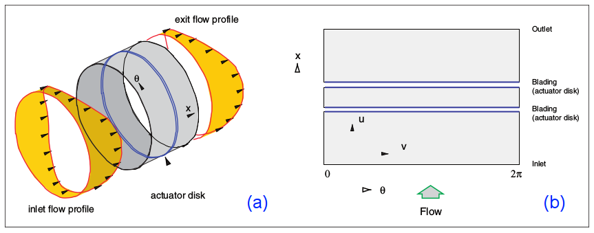
FIGURE 5: (a) Reduction of the flow geometry to a mid radius representation and (b) sketch of the computational domain.
-
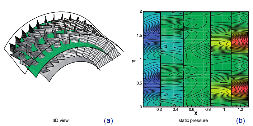
FIGURE 6: BR710 Test-case. (a) A sketch of the compressor geometry. (the mid-radius surface is shown in green). (b) planar representation of instantaneous pressure field at the mid-radius for the two-cell Rotating Stall configuration.
-
-
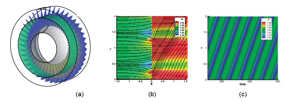
FIGURE 7: NASA Rotor 1B. (a) sketch of the domain reduction to a cylindrical surface. (b) Isomach and streamline patterns for the Two-Cell Stall configuration. The blockage effect of the stall cells are visible from streamline divergence and by the low-speed zones in front of the rotor. (c) Time history of the outlet pressure for the Two-cell Stall configuration. For all plots the tangential direction is scaled as η = θ/2 π .
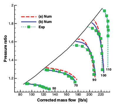
FIGURE 8:
Nasa Rotor 1B. Comparison between numerical and experimental fan map: (h) Experimental map, (a) numerical results with classical loss models (set A), (b) numerical results with polynomial fitting of losses and deviations (set B). -
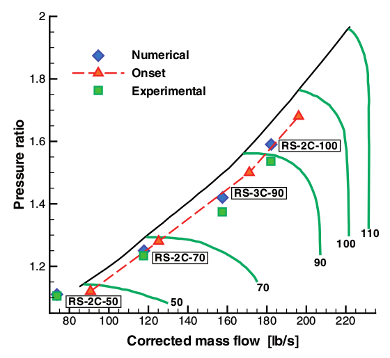
FIGURE 9:
Nasa Rotor 1B. Comparison between computed and experimentally observed Rotating Stall configurations at different rotational speeds. Each label refers to the nearest triplet of symbols. -
Control of Flow Separation over a NACA0015 Airfoil
read MORE » -

Nozzle Flow Control and Fluidic Thrust-Vectoring
read MORE » - back to RESEARCH »
Copyright @ 2015 JLab. All rights reserved.
